Overview
| module url | N/A | |||||||||||||||||||||||||||||||||||||||||||||
| git repository | https://bitbucket.org/arrizza-public/arduino-fast-square-wave | |||||||||||||||||||||||||||||||||||||||||||||
| git command | git clone git@bitbucket.org:arrizza-public/arduino-fast-square-wave.git | |||||||||||||||||||||||||||||||||||||||||||||
| verification report | https://arrizza.com/web-ver/arduino-fast-square-wave-report.html | |||||||||||||||||||||||||||||||||||||||||||||
| version info |
|
- repo status: Repo Information
- installation: Common Setup
Summary
This project toggles a pin on the Arduino as fast as possible to produce a square wave, roughly 2.0Mhz. My oscilloscope reported 1.9876 Mhz.
See Arduino Tools and other Setup for some discussion about setting up an Oscilloscope.
Setup
Set pin 10 to an output
Main Loop
Instead of using the normal pinWrite, we use the cbi and sbi macros. These take a pin id and either clear it (cbi) or
set it (sbi). To get a uniform square wave a couple of NOPs (i.e. "no-operation" instructions) are entered after the
clear bit. These compensate for the hidden jump instruction generated by compiler due to the for(;;) loop call.
for (;;)
    {
    // Clear Bit: set pin 10 low
    cbi(PORTB, PORTB2);

    // compensate for the jump instruction in the for() loop
    __asm__ ("nop"::);
    __asm__ ("nop"::);

    //Set Bit: set pin 10 high
    sbi(PORTB, PORTB2);
    }
Note: each arduino may not have pin 10 at PORTB2. If you don't get the signal, you will have to look up the actual pinout. In my case it is a Nano and so "D10" maps to "PB2" which means PORTB2 in cbi/sbi instructions. (FYI the pin that maps to PORTB4 is "D12").
Connecting to the Arduino Pins
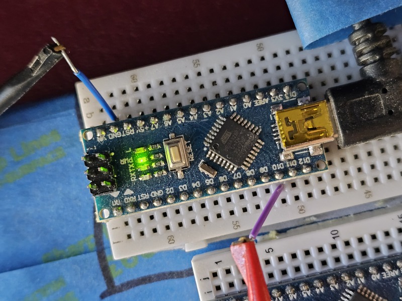
This image shows the oscilloscope leads connected to pin 10 (red lead) and to ground (black lead).
The Waveform
This image shows the waveform of the square wave. You can see it is nicely square, taking roughly 250ns (i.e 2 and a half horizontal grids) while it is high and roughly 250ns when it is low which corresponds to 1.9876Mhz as reported by the oscilloscope. Note each horizontal grid is 100nS (see the "M 100ns" at the bottom of the screen).
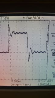
- the 1.9876Mhz waivers a bit from 1.98751 to 1.98762. This is expected since the clock used by the Nano is not perfect and will waiver a bit depending on the surrounding temperature and various electronic factors on the chip and board.
- at this high frequency the square wave has some "ringing" when it rises up and when it falls down. This is normal.
- if you see rounded "corners" on the square wave, use better quality oscilloscope leads. I happen to have an older set of oscilloscope leads and when I tried them the square wave wasn't as square.
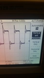
I used "Auto-range" on the Oscilloscope. It adjusted the horizontal range a bit for me. Now it shows the 250ns cycle a little more clearly - the "M 250ns" at the bottom of the screen indicates each horizontal grid is 250nS wide. Two of these form one cycle so 1/500nS = 2Mhz.
Notes
The Arduino's Atmel CPU runs at 16Mhz, but that doesn't mean that each instruction takes one clock cycle (i.e. 62.5 nanoseconds). Each instruction can take more than one clock cycle. In fact, there are some instructions that can sometimes take one cycle and sometimes take two cycles.
To find out what is going on, we need to see the exact opcodes and then go through the Atmel datasheet to find out how long each individual instruction takes.
Get the Generated Assembly Listing
To see the cbi, NOPs, the sbi and jump instructions, use avr-objdump
cd cmake-build-debug/CMakeFiles/arduino-fast-square-wave.dir/src

# you should see an obj file:
$ ls *.obj
main.cpp.obj

# invoke avr-objdump to:
#    -S intersperse the C++ source code in the listing
#    -d causes a disassembly
avr-objdump -S -d main.cpp.obj
The ATMEL Opcodes for the Main Loop
Unfortunately, the avr-objdump is not easy to read. I took out the "-S" and removed some of the extra listing to make it clearer for our purposes here.
00000000 <loop>:
   0: 2c 98        cbi 0x05, 4 ; 5
   2: 00 00        nop
   4: 00 00        nop
   6: 2c 9a        sbi 0x05, 4 ; 5
   8: 00 c0        rjmp .+0       ; 0xa <__zero_reg__+0x9>
Here you can clearly see the cbi, two NOPs, the sbi, all followed by a jump backwards to the top of the loop.
See ATmel's site AVR Instruction Set
for the opcodes, the clock cycle count and specific details on how they work.
Timing Analysis of the Assembly
Using Atmel's datasheet to look up each individual opcode, the total cycle count is
cbi   => 2 clock cycles
NOP   => 1 clock cycle x 2 => 2 clock cycles
sbi   => 2 clock cycles
jump  => 2 clock cycles

total: 4 clocks high, 4 clocks low

# double-check our work!
16Mz / 8 clock cycles => 2Mhz
Can We Go Faster?
The other Jump instructions available on the ATMEL CPU also take 2 cycles and the Branch instructions (i.e. conditional jumps) take 2 cycles if the jump is taken. So at this point, it looks like this is the fastest square wave we can get with an Arduino.
What If It Wasn't a Square Wave?
But perhaps we can go a little faster if we take away the requirement for the wave to be square.
I tried taking away the NOPs to see the effect:
- one NOP => the frequency jumped to 2.27Mhz (note: 16Mhz / 7 clock cycles => 2.285)
- zero NOP => the frequency jumped again to 2.65Mhz (note: 16Mhz / 6 => 2.66Mhz)
These values make sense since the waveform cycles that much faster without the NOPs. However, in both cases the waveform was not square since it was on longer than it was off.