Overview
| module url | N/A | |||||||||||||||||||||||||||||||||||||||||||||
| git repository | https://bitbucket.org/arrizza-public/arduino-interrupts | |||||||||||||||||||||||||||||||||||||||||||||
| git command | git clone git@bitbucket.org:arrizza-public/arduino-interrupts.git | |||||||||||||||||||||||||||||||||||||||||||||
| verification report | https://arrizza.com/web-ver/arduino-interrupts-report.html | |||||||||||||||||||||||||||||||||||||||||||||
| version info |
|
- repo status: Repo Information
- installation: Common Setup
Summary
Demonstrate an example Timer Interrupt and ISR for an Arduino.
An Arduino can be interrupted periodically through its Timers. The Mega has 4 timers, each slightly different from the others. This project only uses Timer2.
The basic operation of the Interrupt is:
- set up Timer2
- at some point, timer2 will "pop" and then:
- stop executing whatever it was doing at the time
- jump to an Interrupt Service Routine (ISR)
- jump back to the original spot and continue executing from there
In this case, the main loop is checking the Serial port ("polling" it) for any characters, and if any, it handles those incoming characters. At any time during that processing Timer2 could pop, interrupting anything that was executing at that moment to jump to the ISR.
This all occurs very quickly - in only a few instructions. The overall effect is that it looks like the Arduino is doing two things at once, e.g. flashing the LED and handling incoming characters. It is an illusion, however. The processor can only do one thing at a time. It is either handling incoming characters, handling the interrupt, executing the ISR, or going back to the normal execution path.
Note you might need an oscilloscope for this project. See Arduino Tools and other setup for some discussion about setting one up.
Setup
This function sets up the Serial Port and pin 10 for output. Set the oscilloscope to check pin 10
It then sets the Timer2 registers to run at around 4Khz.
// set to 4Khz
timer_info.prescaler1 = 0;
timer_info.prescaler2 = 1;
timer_info.prescaler3 = 0;
timer_info.ocr_val    = 249;
timer_info_change_timer();
This frequency causes the timer to pop every 125 uS. That's microseconds (millionths of a second). See the spreadsheet " Timer Calculations.xlsx" in the repository for a whole series of settings, actual readings and calculations. It also has a reverse calculator, see below for more information.
Look for prescalar "010" and OCR2A value of 249 in the spreadsheet columns "prescalar" and "ocr2a".
The Actual Frequency column shows frequency measurements reported by my oscilloscope. In this case it was 40001.430Hz => ~4Khz
The Expected Pulse Width column is the calculated time based on the register values of 010 and 249. In this case 125uS.
See below for a full description of the prescalar and OCR2A register values and the calculations in the spreadsheet.
Main Loop
The main loop looks complex, but it is simply waiting for a character on the Serial port and when it has a full command, it changes Timer2 to those values.
The format of the command is
ppp nnn <lf>
where:
- ppp is the prescalar value. each p is "0" or "1"
- a single blank
- nnn is the OCR2A register value from 1 to 255
- lf is the linefeed character 0x0A
This is a lot to type in correctly, so there is a ruby script that does this for you. See below for "auto_test.rb" information.
As the characters come in through the Serial Port, the values are saved in a struct called timer_info.
struct _timer_info
  {
    // where we are reading
    int state;

    // prescalar digits
    int prescaler1;
    int prescaler2;
    int prescaler3;

    // ocr2a value can be 0 - 255
    int ocr_val;
  };
typedef struct _timer_info timer_info_t;
static timer_info_t        timer_info;
The timer_info.state field helps us parse the incoming stream of characters. Here are the values it can take on:
//  1: about to read prescaler1
//  2: about to read prescaler2
//  3: about to read prescaler3
//  4: read a space
//  5: reading ocr value
//  6: set timer
As the characters arrive one by one, and are processed, the state variable is changed to reflect where we are in the incoming command. When the next character arrives, we check the state field and double-check and decode that character appropriately.
State 1
In this case, the state was 1 which means we were about to read prescalar bit 1.
case 1:
timer_info_init();

timer_info.state = 2;
timer_info_set_prescaler(ch, 1);
break;
Since this is the first state we hit after reading a line, we initialize the timer_info struct.
State 2
We then immediately indicate the next state is 2 (i.e. about to read prescalar bit 2) and finally set the prescaler2 value in timer_info to whatever was given to us in the Serial port.
switch (ch)
    {
    case '0':
        *prescaler = 0;
        break;
    case '1':
        *prescaler = 1;
        break;
    default:
        Serial.print("NAK unknown ");
        Serial.print(name);
        Serial.print(" char: ");
        Serial.println(ch);
        timer_info.state = 1;
        break;
    }
If there was an invalid character, we print a message to the Serial Port and reset the state to expect the start of a new line.
State 5
Reading the OCR2A value in state 5 requires us to build the value digit by digit.
// < ... snip ... >
else if (ch >= '0' && ch <= '9')
{
timer_info.ocr_val = (timer_info.ocr_val * 10) + (ch - '0');
}
Assuming that the initial ocr_val is 0, this takes that variable, multiplies it by 10 (which shifts it to the left by one decimal digit), and then adds the character value to it. The "ch - '0'" works because the ASCII codes for "0", "1", etc. are arranged sequentially so:
 "0" - "0" => 0
 "1" - "0" => 1
 // ... skip ...
 "9" - "0" => 9
Here's an example. The incoming string of characters is "2" "4" "9" so we expect ocr_val to have 249 in it when we're done
   ocr_val = 0    # initial value

   # handle the "2"
   ocr_val * 10 => 0
   "2" - "0" = 2
   ocr_val + 2 => 2

   # handle the "4"
   ocr_val * 10 => 20    # it was 2 from the calculation above
   "4" - "0" = 4
   ocr_val + 4 => 24

   # handle the "9"
   ocr_val * 10 => 240    # it was 24 from the calculation above
   "9" - "0" = 9
   ocr_val + 9 => 249

   # done. ocr_val is 249 as expected
In state 5, we will have the prescalar value and the OCR2A value.
When the character is a linefeed 0x0A, we set Timer2 to the new values. We also reset the state to 1, ready for the next incoming line of characters.
case 5:
    if (ch == 0x0A)
        {
        timer_info.state = 1;
        timer_info_change_timer();
        }
The timer_info_change_timer() function sets the Timer2 up for the new values. It first disables interrupts because we do not want a Timer pop to occur while this setup process is going on. If one did happen, the register values may not be consistent with each other at that instant (e.g. TCCR2B had only one bit of three set correctly), so the next Timer pop may be incorrect.
// stop interrupts while we're changing the Timer params
cli();

// set prescaler
TCCR2B = 0;
if (timer_info.prescaler3 == 1)
{
TCCR2B |= _BV(CS20);
}
if (timer_info.prescaler2 == 1)
{
TCCR2B |= _BV(CS21);
}
if (timer_info.prescaler1 == 1)
{
TCCR2B |= _BV(CS22);
}

// set WGM to CTC mode (010)
// In this mode Timer2 counts up until it matches OCR2A
TCCR2A = _BV(WGM21);

OCR2A = timer_info.ocr_val;

// When the OCR2A register matches the Timer2 count, cause an interrupt
TIMSK2 = _BV(OCIE2A);

// enable interrupts
sei();
The prescalar value is held in register TCCR2B. There are 3 bits in that register that hold the prescalar code for Timer.
These bits are set individually using the CS20, CS21 and CS22 values. The 3 bits for a 000 through 111 code that represent the true scalar value
CS22 CS21 CS20   prescalar
 0        0         0       Timer stopped
 0        0         1       prescaler  1 (arduino clock / 1)
 0        1         0       prescaler  8 (arduino clock / 8)
 0        1         1       prescaler  32
 1        0         0       prescaler  64
 1        0         1       prescaler 128
 1        1         0       prescaler 256
 1        1         1       prescaler 1024
The TCCR2B register tells the processor how to use the OCR2A value.
// set WGM to CTC mode (010)
// In this mode Timer2 counts up until it matches OCR2A
TCCR2A = _BV(WGM21);

// When the OCR2A register matches the Timer2 count, cause an interrupt
TIMSK2 = _BV(OCIE2A);
There are multiple WGM modes, but in this case we use WGM21 which sets Timer2 mode to count up until it matches OCR2A and then the ISR is invoked. The other modes use overflow and other methods to cause a unique condition where the processor invoked the ISR.
The OCR2A register holds a value from 0 to 255.
And finally interrupts are enabled again.
// enable interrupts
sei();
Notes
The TCCR2A and TIMSK2 registers are used to set up how the interrupt uses the OCR2A and TCCR2B fields. The description of how these registers work is outside the scope of this project.
You can see the full datasheet here: Atmel 2560 datasheet
See section "20.10.1 TCCR2A –Timer/Counter Control Register A" and "20.10.7 TIMSK2 – Timer/Counter2 Interrupt Mask Register" for a full discussion.
Prescaler register
The prescaler register TCCR2B is described in section "20.10.2 TCCR2B – Timer/Counter Control Register B". We only use three bits of it named CS20, CS21 and CS22. There is a "Table 20-9. Clock Select Bit Description" showing the bit patterns needed to set the prescaler from 1 to 1024.
OCR2A register
The OCR2A register holds the "TOP" value that the CPU compares against after every clock tick (after prescaling). If the current clock tick matches the "TOP" value (i.e. the contents of the OCR2A register) the interrupt is generated.
See section "20.4.2 Clear Timer on Compare Match (CTC) Mode" for a detailed description of how the OCR2A register works in CTC mode (this is the mode chosen by the WGM21 setting in TCCR2A).
Calculating the Expected Timeout and Frequency
The Calculation
- Start with f=16Mhz
- use 1/f to find the clock period (62.5 nS)
- use prescaler value (1, 8, 32, etc.) and OCR2A value to calculate the expected pulse width:
- 62.5nS prescaler value => the post-scaler clock period. This takes the clock frequency and scales it down by the prescaler value. In other words this extends the resulting clock period. I'm calling this value the post-scaler clock period. A prescaler value of 8 should result in post-scaler clock period 8 times longer than the normal CPU clock period of 62.nS, i.e. 862.5=500 nS.
- OCR2A value + 1 => clock ticks. This is the number of post-scaler clock ticks to count before the interrupt is triggered.
- clock ticks * post-scaler clock period. This is the total expected timeout between interrupts. At this point, we have the number of clock ticks to trigger on, and we have the post-scaler clock period, so the total time to wait between interrupts is the number of clock ticks times the clock period.
The calculated timeout is therefore:
(OCR2A value + 1) * (62.5nS * prescalar value)
The frequency this runs at will be (1/timeout) * 2. It's * 2 in this case because we change the state of the pin every
interrupt and a single cycle of the waveform requires two toggles
(e.g. from on to off back to on).
The Columns
In the spreadsheet
- the OCR2A value is in the column labelled "ocr2a"
- the prescaler value is in "Timer prescalar value" and the bit pattern used to specify that value is in the column " prescaler"
- the CPU clock period is in the column "MCU clock period" (i.e. 62.5 nS)
- the expected timeout between interrupts is in column "Expected pulse width un-rounded" and that value is rounded to 3 decimal places in "Expected pulse Width"
- The actual pulsing frequency as measured via an oscilloscope is in "Actual Frequency Hz"
- The actual timeout is displayed in column "Actual pulse width"
- The difference as a percentage between the Expected and Actual timeouts is in the column "Diff (%)". Note that generally this is 0% meaning that the actual value and the calculated value are very similar, i.e. near 0.0%. A typical set of values is actual 127.959 uS vs calculated 128.000 uS.
Some of the DIff% values are greater than 0.1% and are highlighted in yellow. These occur at high frequencies i.e. short timeouts. The cause is that the amount of time it takes to process the ISR is longer than the amount of time available before the next interrupt occurs.
For example, see the row with prescaler bit pattern 010 and an OCR2A value of 1. The calculated timeout is 1uS but the actual timeout is 3.897 uS. This means that any rows with settings that cause a timeout shorter than about 4uS will probably fail. Other highlighted rows show similar results. The solution to this problem is to perform the operations in the ISR more quickly or to move those operations out of the ISR, neither which are easy to achieve.
Reverse Calculating the Prescaler and OCR2A values for a Timeout
Typically, you want to do the reverse. You need a particular timeout or frequency, and you need to reverse calculate the Prescaler bits and OCR2A value you need to set.
The "Reverse Calculator" sheet in the spreadsheet does exactly that.
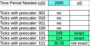
Enter the timeout you need in cell B1. This is the time period between ISR invocations. In the example, it is 2000 uS or 2 ms.
The worksheet then attempts to find the prescaler value and the OCR2A value that will give you that timeout.
If a particular prescaler value can't give that timeout, then the cell will display "no".
If a prescaler value can deliver that timeout, it will display a number between 0 and 255 and highlight the cell in green.
However, it may be possible that it is not an exact period. In the example, the prescaler bit pattern "111" gives an OCR2A tick count of 30.25. Since OCR2A can only take integers, you will have to choose either 30 or 31. Both of these numbers will generate timeouts slightly off from the requested 2ms. That condition is indicated by "not exact" in the next column.
If the number does give an exact timeout that you asked for, then the next column will display "exact" and be highlighted in green. In the example, prescaler 101 (t/128) and an OCR2A value of 249 gives exactly 2ms timeout. Prescalar 110 (t/256) and OCR2A value of 124 does the same.
If you play with the values in this calculator you will find that the longest timeout is 16384uS. Anything longer than that, you will have to divide that down yourself within the ISR. You could use, for example, your own prescaler value to count down. If it's not zero, you immediately exit the ISR. When it's zero you let the rest of the ISR execute normally. This effectively divides the timeout by your prescaler value.
If you try to find the shortest timeout, it is 0.0625 uS (prescaler 001 (t/1) and OCR2A value of 1). Since this is the Arduino's clock frequency (1 / 16Mhz = 62.5 nS), you can't interrupt the ISR any faster.
auto_test.rb or auto_test.py
In the terminal, for ruby:
$ ruby auto_test.rb
tx: SND 111 1 pulse width:0.128mS freq:3906.250Hz
rx: ACK 111 1
For python:
# ensure venv is set (do once)
$ ./do_install
$ source do_env
(venv) $ $pyexe auto_test.py
tx: SND 111 1 pulse width:0.128mS freq:3906.250Hz
rx: ACK 111 1
Press enter when you're ready to continue!
# ... skip ...
$ deactivate
This shows that the command line "111 1" was sent to the Arduino, which responded with an "ACK 111 1" indicating that it received the line ok and parsed it ok.
The pulse_width value is the expected width of the one half of the square wave, i.e. the pulse width of the
signal. The freq value is the expected frequency.
The oscilloscope at this point indicates a 3.9075KHz square wave. The expected frequency is 3.906kHz. Different Arduinos and oscilloscopes may report slightly different values. The difference in this case is 3.9075 - 3.906250 = 12 hertz which is around 0.3% error.
I put the pause in the scripts to read the oscilloscope and update the spreadsheet with those actual values.
Press enter to cause the next setting to be sent down to the Arduino.
tx: SND 111 32
rx: ACK 111 32
Press enter when you're ready to continue!
In this case "111 32" which causes an oscilloscope reading of 236.823Hz.
The settings the script sends down are in these lines
# setup the various prescalers
[0b111, 0b110, 0b101, 0b100, 0b011, 0b010, 0b001].each do |prescaler|
# set some OCR2A values for each prescaler
[1, 32, 63, 95, 127, 255].each do |val|
The prescaler values are in binary "0bnnn" and the OCR2A are in the array right below it. You can change the prescaler values to any of the bit patterns from 0b001 to 0b111. The 0b000 value won't cause an interrupt to trigger.
The OCR2A values can be anything in the range from 1 to 255 (0 may cause errors)
The rest of the script sets up the full command line ("ppp nnn"), sends it to the Arduino and then handles the response from it.
When the interrupt period is too short, the output from the arduino is truncated, for example:
tx: SND 010 1
rx: ACK 01Press enter when you're ready to continue!
To recover:
- press the reset button (brown) on the Arduino
- press enter on the PC so the ruby script moves on to the next setting