Overview
| module url | https://pypi.org/project/pycro-hal.html | |||||||||||||||||||||||||||||||||||||||||||||
| git repository | https://bitbucket.org/arrizza-public/pycro-hal | |||||||||||||||||||||||||||||||||||||||||||||
| git command | git clone git@bitbucket.org:arrizza-public/pycro-hal.git | |||||||||||||||||||||||||||||||||||||||||||||
| verification report | https://arrizza.com/web-ver/pycro-hal-report.html | |||||||||||||||||||||||||||||||||||||||||||||
| version info |
|
- repo status: Repo Information
- installation: Common Setup
Summary
A python interface to a microcontroller with a Hardware Abstraction Layer (HAL).
This module allows a python script to control an Arduino. It reads or writes to any of the Digital or Analog pins.
Currently only works with Arduino Nano.
See pycro page for the full communications protocol or the doc/comm_protocol.md.
Future enhancements
- Double check it works cross-platform i.e. macOS and Windows
- Expand the functionality, e.g. allow ISP communications between two Arduinos to be controlled by the python script.
- Add additional support for Arduino shields. There probably is a need to have an "easy to add" interface to multiple shields.
- Abstract out specific and common functions so that the same script (with minor changes) can be used on multiple or any Arduino. If this goes well, it may be possible to abstract ot other microcontroller chips.
Initial setup
- see doc/test_process.md for set of instructions to correctly setup the python venv, and to make sure all other
tools are installed. You can check by using
./do_check - The Arduino you use must be flashed with pycro-arduino page
Nano breadboard
see pycro schematic for a schematic.
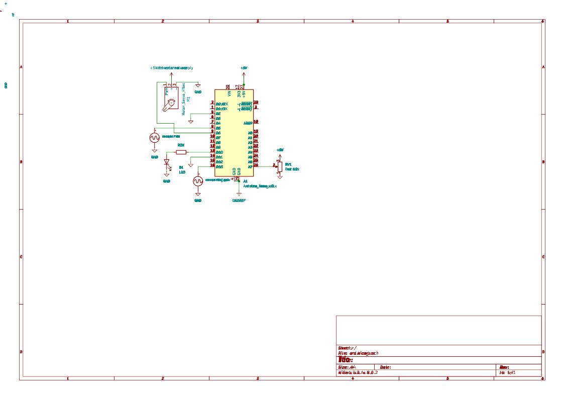
- setup Nano on breadboard
- attach USB-C to Nano
- Nano GND pin to breadboard -ve
- Nano +5V pin to breadboard +ve
- setup a 10K potentiometer
- middle pin attached to Nano A7
- one other pin attached to breadboard -ve (Gnd)
- one other pin attached to breadboard +ve (5V)
- check with
doit adcordoit graph(turning the pot, should change the voltage read)
- oScope for fastest GPIO cycling:
- gnd lead to breadboard -ve (Gnd)
- +ve lead to Nano D13
- check with
doit gpio_fast(should see a square wave)
- oScope for PWM duty cycle:
- gnd lead to breadboard -ve (Gnd)
- +ve lead to Nano D5
- check with
doit pwm(should see a square wave with a 50/50 duty cycle with a 1.024mS period)
- external LED:
- Nano D12 to 2k resistor
- other end of 2k resistor to LED long leg (+ve)
- LED short leg (-ve) to breadboard -ve (GND)
- check with
doit gpio_write(LED should blink)
- Nano digital pins
- Nano D2 to breadboard +ve (5V)
- Nano D11 to breadboard +ve (5V)
- check with
doit digport(D2 and D11 should be 1, others should be 0)
Sample App
See sample/app.py for an example of how to use PycroHalInterface.
In short, there are 4 steps:
Step 1 set up serial port
Communication with the Arduino is UART/Serial. Specify that by setting the configuration:
self._pycro.cfg.protocol = 'uart'
self._pycro.cfg.uart_port = '/dev/ttyUSB0'
- currently only the 'uart' protocol is recognized
- the uart_port must match the serial/uart port the Arduino is connected to.
Step 2 start the communications
self._pycro.start()
Note: the Arduino sends 2 or 3 empty responses to ensure the communication channel is running correctly. If these stop or fail or hang, then there is a communication issue that needs to be resolved.
Step 3 send a command and receive of a response
As an example, send a ping and receive the pong response.
self._pycro.ping()
self._pycro.recv()  # note: not all commands have a response.
See doc/comm_protocol.md for specific behaviors for all the possible commands.
You can do as many commands as you need in this step.
Stop communications
It is very good practice to cleanly terminate communications. Most OSs are pretty good at automatically cleaning up, but it is worth the effort to close, shut down, and clean up any communications, threads etc. when the app closes.
self._pycro.stop()
Run it
- Power on the Arduino
- Check the comm port is connected
- run ./doit to run the app
ls /dev/ttyUSB*   # on Ubuntu; other OSs are different

./doit    # defaults to ping-pong
Typical output:
00:00.001      App.run tests:ping
00:00.203      checking communications...
00:01.462 rx:  0000:  00           # two empty rsp automatically sent by Arduino
00:01.462 rx:  0000:  00
00:01.462      comm_ok: 1
00:01.462      comm_ok: 2
00:01.462 OK   connection: 2 comm_ok rsp received; 14 loops
00:01.462 tx:  0000:  03 00 00     # tx a ping
00:01.465 rx:  0000:  03 01 01     # rx a pong
00:01.465 tx:  0000:  03 00 00     # ping again
00:01.468 rx:  0000:  03 01 01     # pong again
The current app has the following CLI:
./doit ping       # ping-pong
./doit version    # get microcontroller version
./doit gpio_read  # read a digital pin; currently set to D10
./doit digport    # read all digital pins
./doit gpio_write # write a digital ping; currently set to D12
./doit fast_gpio  # write a high/low sequence to a pin as quickly as possible; currently set to D13 = internal LED
./doit adc        # read the voltage an analog pin; currently A7
./doit graphic    # show a dynamically updated plot of voltages from adc
./doit logger_off # test turning off the logger and turning it back on again
./doit pwm        # set PWM on digital pin; currently D5
./doit servo      # test servo control; currently on D6
./doit adhoc      # do an adhoc test as implemented on the microcontroller; currently an echo
./doit dev        # used for dev purposes

./doit all        # run all of these (except dev)
ADC notes
Note: to get accurate values in ./doit adc you must set the supply voltage correctly
# in app.py run()
# my USB port supplies 4.69 volts; measure yours from the GND pin to the +5V pin using a multimeter
self._pycro.supply_voltage = 4.69
PWM notes
- When the serial port is disconnected, the pin reverts back to 0 (non-pulsing).
- enter an integer to bump the duty cycle up / down from the default of 127
./doit pwm
<skip>
00:01.463      pwm: setting to: 127
00:01.463 tx:  0000:  05 00 07 05 7F
pwm: press +, - or q to quit: -120              <=== subtract 120 from 127
00:03.337      pwm: setting to: 7
00:03.337 tx:  0000:  05 00 07 05 07
pwm: press +, - or q to quit: -10
00:06.338 WARN pwm: new val is too low: 7 + -10 => -3  <=== went too far
00:06.338 tx:  0000:  05 00 07 05 07
pwm: press +, - or q to quit: +250              <=== the "+" is optional
00:36.457 WARN pwm: new val is too high: 7 + 250 => 257
servo notes
I used an HS-311 servo, see HS-311 specs for specs. Your servo may require different settings.
- Voltage Range: 4.8V - 6.0V
- Max PWM Signal Range: 575-2460 uSec
- Max Rotation: 202 degrees
- I used a separate power supply that can handle 5V up to 1A with a 100 uF capacitor, see servo moters
- It uses similar +/- commands as PWM but these are for degrees (0 - 202), not duty cycle