pycro projects
pycro (PYthon-miCROcontroller) interface uses a python script to communicate with a microcontroller.
The initial algorithm development phase in a project can be done very quickly and easily with python. The full power of python and especially its modules are available at that time e.g. graphing, mathematical analysis tools, etc.
Once the algorithm is fleshed out, the script can be converted to C/C++ and run on the microcontroller at full speed.
Note that this currently uses python, but it should be easy to use Ruby and even javascript (via Node). The scripting language only needs:
- access to a communication protocol e.g. UART/Serial or even USB
- ability to create, read and manipulate byte streams to send on the protocol.
And also note that this currently uses an Arduino Nano. It should be usable across all Arduinos and other microcontrollers ESP32 and STM32 etc.
- Pycro Python HAL - use python to run various microcontroller commands
- Pycro Arduino - the binary to run on an Arduino
Communication Protocol
Definitions
- host - the entity that initiates communications aka as "client", "master", etc.
- uCtrl - the microcontroller (e.g. Arduino) that responds to the communications aka as "server", "slave", etc.
- packet - one or more bytes sent from the host or from the uCtrl
- cmd - a command send from host to uCtrl
- rsp - a response received on host from uCtrl
Packet types
- command - issued from host; always has a response
- directive - issued from host; does not have a response
- response - issued from client; the response from a command or a get
- async response - asynchronously issued from client (no command)
Conventions
- packets start at byte 0 and are a maximum of 255 bytes long
- cmd id is always in byte 2 in all commands and responses
- NAK = 0x00, ACK = 0x01 are defined per response
- If the command is always successful, the response will only have an ACK.
rsp: comm ok
Note: no cmd is sent
Sent from uCtrl at startup to indicate communication is ready.
| comm ok | type: async response |
|---|---|
| byte0 | length = 0 bytes |
cmd: ping
Send from host to uCtrl to check communication.
| ping | type: command |
|---|---|
| byte0 | length = 3 bytes |
| byte1 | cmd bits - reserved |
| byte2 | cmd = 0x00 |
expected response
Pong
| pong | type: response |
|---|---|
| byte0 | length = 4 bytes |
| byte1 | ACK = 0x01 (no NAK) |
| byte2 | cmd = 0x00 ping |
| byte3 | PONG = 0x01 |
cmd: GPIO mode
Send from host to uCtrl to set a GPIO pin's mode for input or output activity
| GPIO mode | type: directive |
|---|---|
| byte0 | length = 5 bytes |
| byte1 | cmd bits - reserved |
| byte2 | cmd = 0x01 |
| byte3: pin | the pin number e.g. 0x0D = 13 for the LED gpio |
| byte4: state | INPUT (0x0) or OUTPUT (0x1) or INPUT_PULLUP (0x2) |
expected response
None
cmd: GPIO write
Send from host to uCtrl to write a value (low/high) to a GPIO pin
| GPIO write | type: directive |
|---|---|
| byte0 | length = 5 bytes |
| byte1 | cmd bits - reserved |
| byte2 | cmd = 0x02 |
| byte3 | pin: the pin number e.g. 0x0D = 13 for the LED gpio |
| byte4 | state: LOW (0x0) or HIGH (0x1) |
expected response
None
cmd: GPIO read
Send from host to uCtrl to read a GPIO pin's state (low/high)
| GPIO read | type: command |
|---|---|
| byte0 | length = 4 bytes |
| byte1 | cmd bits - reserved |
| byte2 | cmd = 0x03 |
| byte3 | pin : the pin number e.g. 0x0D = 13 for the LED gpio |
expected response
GPIO value (HIGH or LOW)
| GPIO state | type: response |
|---|---|
| byte0 | length = 4 bytes |
| byte1 | ACK = 0x01 (no NAK) |
| byte2 | cmd = 0x03 GPIO read |
| byte3 | pin state 0x00 (LOW) or 0x01 (HIGH) |
cmd: ADC Read
Send from host to uCtrl to read an ADC pin's value.
| ADC Read | type: command |
|---|---|
| byte0 | length = 4 bytes |
| byte1 | cmd bits - reserved |
| byte2 | cmd = 0x04 |
| byte3 | pin : the pin number e.g. 0x00 = A0 |
expected response
The ADC value read from the pin. The valid bits depend on the uCtrl spec. The max size is 16 bits.
| ADC value | type: response |
|---|---|
| byte0 | length = 5 bytes |
| byte1 | ACK = 0x01 (no NAK) |
| byte2 | cmd = 0x04 ADC read |
| byte3 | LSB of 16-bit value |
| byte4 | MSB of 16-bit value |
- Arduino Nano: 10 bits are valid
cmd: uCtrl version
Send from host to uCtrl to get the uCtrl version
| uCtrl version | type: command |
|---|---|
| byte0 | length = 3 bytes |
| byte1 | cmd bits - reserved |
| byte2 | cmd = 0x05 |
expected response
Send from host to uCtrl to get the uCtrl version and type.
| uCtrl version | type: response |
|---|---|
| byte0 | length = 0x0D (13 bytes) |
| byte1 | ACK = 0x01 (no NAK) |
| byte2 | cmd = 0x05 version |
| byte3 | uCtrl type |
| byte4 | reserved |
| byte5 - byte12 | 8 character string (no terminating null) |
The uCtrl type is an enum for all supported microcontrollers:
- 0x00 Arduino Nano
- values 0x01 - 0xFF reserved for future
Assumes the version:
- total length is 8 characters (no terminating null)
- has 3 parts: major.minor.patch
- each has a max of 2 characters
- each is separated by a "."
- any space remaining is filled with spaces
cmd get digital port
Send from host to uCtrl to get all digital port values at once
| get digital port | type: command |
|---|---|
| byte0 | length = 3 bytes |
| byte1 | cmd bits - reserved |
| byte2 | cmd = 0x06 |
expected response
The Port B and Port D bits.
| Port B and D bits | type: response |
|---|---|
| byte0 | length = 5 bytes |
| byte1 | ACK = 0x01 (no NAK) |
| byte2 | cmd = 0x06 digital port read |
| byte3 | Port B bits |
| byte4 | Port D bits |
See Arduino pin mapping for the port to pin mapping.
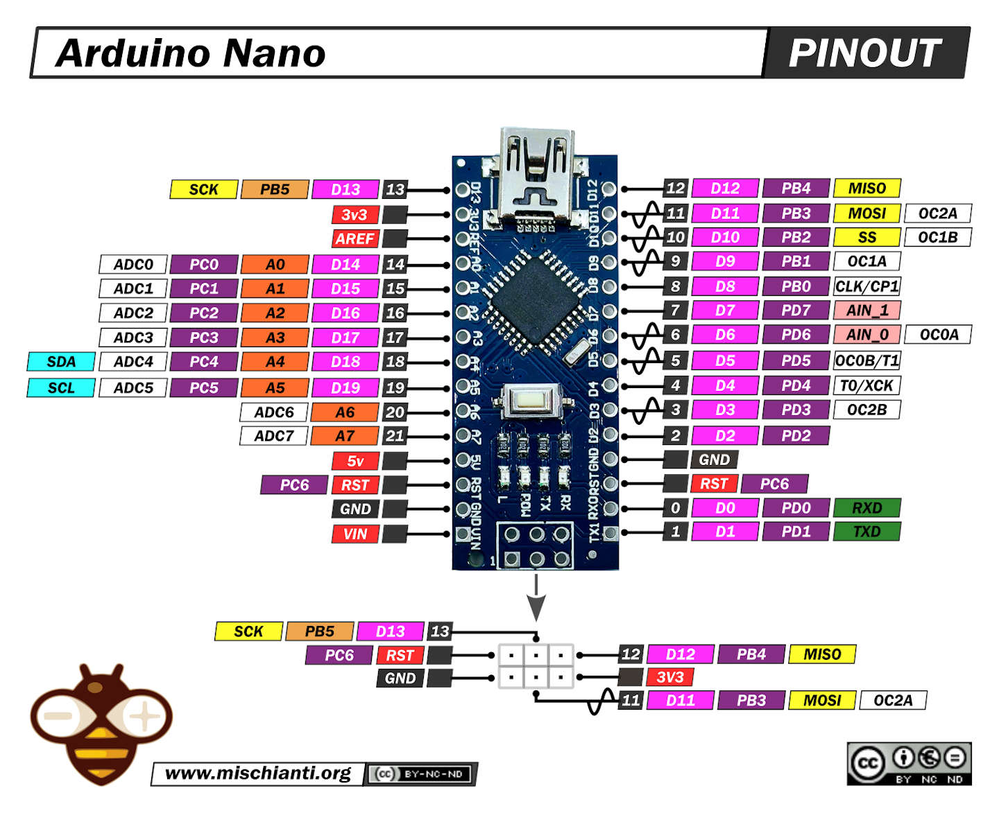
The port bits in byte3 and byte4 map to arduino pins:
- byte3 bit 5 => D13 = Port B bit 5
- byte3 bit 4 => D12 = Port B bit 4
- byte3 bit 3 => D11 = Port B bit 3
- byte3 bit 2 => D10 = Port B bit 2
- byte3 bit 1 => D9 = Port B bit 1
- byte4 bit 0 => D8 = Port B bit 0
- byte4 bit 7 => D7 = Port D bit 7
- byte4 bit 6 => D6 = Port D bit 6
- byte4 bit 5 => D5 = Port D bit 5
- byte4 bit 4 => D4 = Port D bit 4
- byte4 bit 3 => D3 = Port D bit 3
- byte4 bit 2 => D2 = Port D bit 2
- byte4 bit 1 => always 0 (D1 = Port D bit 1, used for RX for uart comm.)
- byte4 bit 0 => always 0 (D0 = Port D bit 0, used for TX for uart comm.)
If byte3 and byte4 are combined into a 16-bit integer the mapping is simple, e.g. bit 12 is D12, bit 5 is D5.
cmd pwm
Send from host to uCtrl to set a pin's PWM duty cycle:
| PWM | type: command |
|---|---|
| byte0 | length = 5 bytes |
| byte1 | cmd bits - reserved |
| byte2 | cmd = 0x07 |
| byte3 | pin : the pin number e.g. 0x03 = D3 |
| byte4 | duty cycle: 0 - 255 |
- Arduino Nano: pin must be D3, 5, 6, 9, 10, or D11
expected response
None
- The PWM period is 1.024 mS and the frequency is 976.418 Hz
- At a duty_cycle 127, the pulse is 0.512 mS
cmd - servo configuration
Send from host to uCtrl to configure a pin for servo control
| servo cfg | type: command |
|---|---|
| byte0 | length = 4 bytes |
| byte1 | cmd bits - reserved |
| byte2 | cmd = 0x08 |
| byte3 | pin : the pin number e.g. 0x03 = D3 |
- Arduino Nano: pin must be D3, 5, 6, 9, 10, or D11
- min >= MIN_PULSE_WIDTH == 544
- max >= MAX_PULSE_WIDTH == 2400
expected response
None
cmd - servo write
Send from host to uCtrl to set servo to a position (in microseconds)
| servo write | type: command |
|---|---|
| byte0 | length = 5 bytes |
| byte1 | cmd bits - reserved |
| byte2 | cmd = 0x09 |
| byte3 | LSB position e.g. 575 |
| byte4 | MSB position pulse-width e.g. 575 |
expected response
None
cmd - placeholder for next cmd
| placeholder | type: placeholder |
|---|---|
| byte0 | length = ? bytes |
| byte1 | cmd bits - reserved |
| byte2 | cmd = 0x0A (placeholder only |
cmd: ad hoc
Send from host to uCtrl to perform an ad hoc function as implemented on the uCtrl.
| ad hoc | type: command |
|---|---|
| byte0 | length = N bytes (3 <= N <= 255 |
| byte1 | cmd bits - reserved |
| byte2 | cmd = 0xFF |
| byte 3 to byte 255 | depends on ad hoc command |
expected response
The ad hoc response as implemented on the uCtrl.
| ad hoc | type: response |
|---|---|
| byte0 | length = N bytes (3 <= N <= 255) |
| byte1 | ACK = 0x01 (no NAK) |
| byte2 | cmd = 0xFF adhoc |
| byte3 to byte 255 | implementation dependent |