Overview
| module url | N/A | ||||||||||||||||||||
| git repository | https://bitbucket.org/arrizza-public/3d-print-mount-brackets | ||||||||||||||||||||
| git command | git clone git@bitbucket.org:arrizza-public/3d-print-mount-brackets.git | ||||||||||||||||||||
| verification report | https://arrizza.com/web-ver/3d-print-mount-brackets-report.html | ||||||||||||||||||||
| version info |
|
- repo status: Repo Information
- installation: Common Setup
Summary
This project is my first 3D printing project. I used openscad since it was much easier to figure out (for me!) than Fusion360.
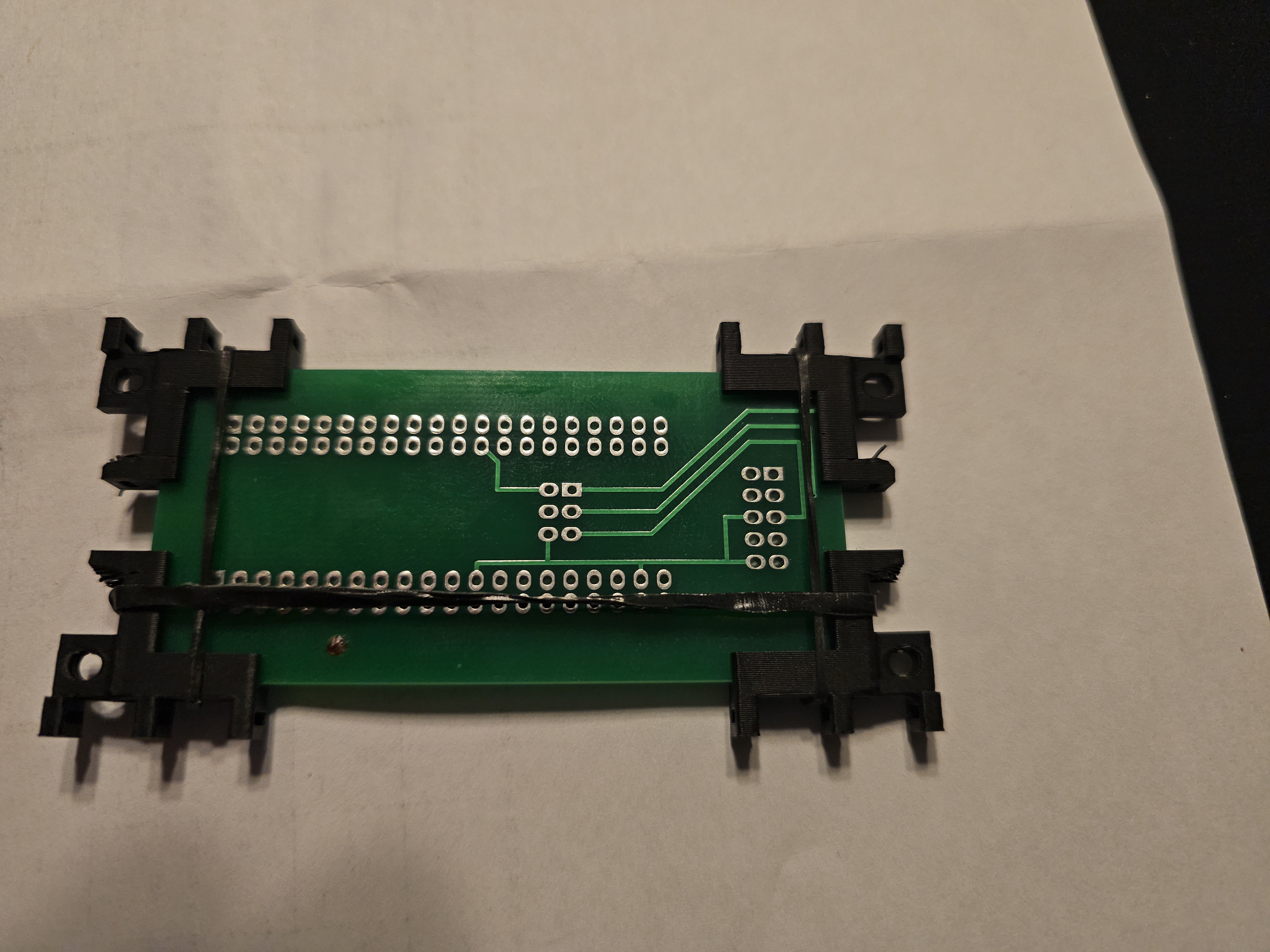
The project generates mounting brackets to be used in the corners of a PCB. They provide bolt holes to be able to mount the PCB without drilling holes in it.
To run
See doc/how-to-print.md for a full set of instructions.
For multiple brackets e.g. 4 of them use the Bambu Studio clone features as described. Click "+" 3 times to get a total of 4 brackets on the plate.
To use the brackets
- Put a bracket in each corner
- rotate it as needed to put the bolt holes where your project requires them
- use small wire ties or small elastics to hold the brackets in place.
- use 6-32 bolts to mount them as needed. Note: I tried M3 and they seem to fit pretty good as well
This shows brackets on a small PCB using elastics to hold them in.
Those elastics can be found in the "hair care" section of stores. They typically have many sizes for putting hair in a ponytail.
The reason these work is that they are stretchy but with fairly low force. That makes brackets stay put on the PCB corners long enough to bolt everything down.
This shows the same but also has a wire tie.
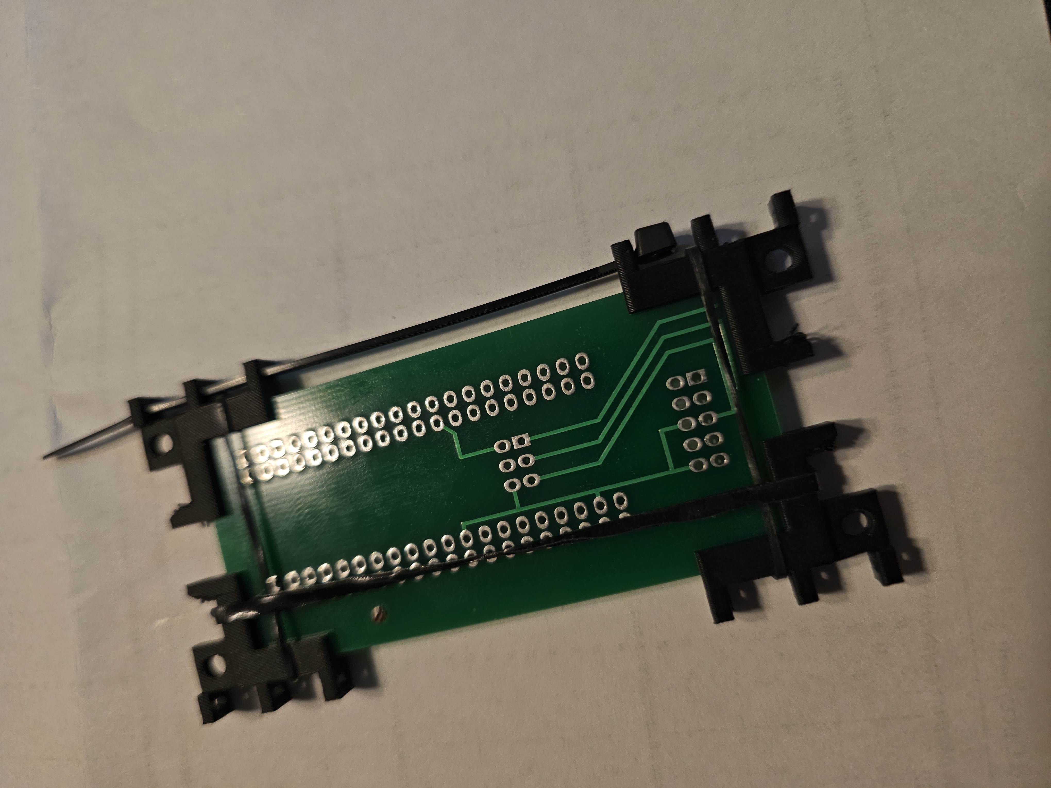
Wire ties can be used hold the brackets in place more permanently.
Note: the wire ties are the smallest I could find at the hardware store. The bigger ties will be more applicable to larger PCBs.
These are the dimensions used in the scad file:
strip_thick = 0.97;
strip_width = 2.46;
Next steps
- create generic "feet" that the bolts can screw into.
- create similar brackets for a servo I'm using in a project.
- create similar brackets for larger PCBs (if necessary)
How to 3D print
Note: this assumes you are using a BambuLab 3d printer. I have a BambuLab A1 Mini.
install openscad, etc
See doc/test_process.md to do the initial install:
# install openscad
# install Bambu Studio
./do_subm_update
./do_install full
run openscad
- run openscad
- load the .scad file
- click "File"
- click "Open File"
- navigate to the directory
- click Open
- render it by doing one of these (the image will go all yellow):
- click Design | Render
- press F6
- or, click icon with cube and corner arrows
- export it by doing one of these:
- click File | Export | Export as STL
- press F7
- or, click icon with page and "STL" on it
- navigate to this directory and save the .stl file into
./outdirectory
run Bambu Studio
In your 3d printer
- import the .stl file from
./out - slice it
- print it
- see README.md and check if it works as it is intended
If it works for you, and you're using a BambuLab A1 Mini, do these steps to create multiple copies of the model:
- open Bambu Studio
- import the stl file into your 3D printer
- ensure you are in the "Prepare" tab
- right-click on the model
- select "clone"
- click "+" as needed to get a total number of copies you need
- select them: press ctrl and then click on each of the copies
- right-click on the plate (not the model)
- select "arrange"; Bambu Studio will move and orient the copies for efficient printing
- click "Slice plate"
- click "Print plate"
- get a "Send print job" dlgbox
- click "Send"